When transmitting a message over a noisy transmission channel, a low-density parity-check (LDPC) code is essential.
Forward error correction (FEC) coding is a collection of techniques used in modern digital communication systems to minimize errors in data transmission over noisy channels. FEC techniques are employed in both wireless systems, such as Wi-Fi, cellular and satellite communications, as well as wired systems like DSL, cable and fiber optic.
Bit Basics
The basic unit of information in digital communication is a bit (binary digit), the value of which is most commonly represented as a 0 or 1. A bit error occurs when a transmitted 0 is received as 1 and vice versa due to noise (electrical or electromagnetic disruptions), interference (other transmitters) or other sources of distortion. Digital communication systems use a metric known as bit error rate (BER) to measure the average number of bit errors per unit of time. For example, a BER of 10-1 means that one out of every 10 bits was received in error. FEC tries to minimize this error rate by adding redundancy to the bit sequence at the transmitter or encoding the message. On the receiver side, the corresponding decoder uses the added redundancy to detect and/or correct the errors.
The most basic coding scheme is a repetition code where a bit is repeated several (n) times. For example, a repeat code with n = 3 takes an input message 011 and produces the codewords 000 111 111 as the encoded message. Let’s assume each of the codewords experiences one bit error and is received as 010 110 101. The decoder applies a majority voting scheme to each codeword and decodes 010 as 0, 110 as 1 and 101 as 1, resulting in an error-free received sequence (011). However, repetition coding is very inefficient and other codes exist that have better error performance while minimizing the amount of redundancy.
The Channel Capacity
Claude Shannon, in a seminal paper published in 1948, showed the existence of such codes. He illustrated that any communications channel — a telephone line, a radio band, a fiber-optic cable — could be characterized by two factors: bandwidth and noise. Bandwidth is the range of frequencies that can be used to transmit a signal; noise is anything that can disturb that signal. Given a channel with particular bandwidth and noise characteristics, Shannon showed how to calculate the maximum rate at which data can be sent over it with zero error. He called that rate the channel capacity. His proof, however, didn’t actually provide a method to construct such codes. Over the next few decades, various codes were discovered to improve on the error-correcting capacity but none quite reached channel capacity, also known as the “Shannon limit.”
Then, in 1993, at the Institute of Electrical and Electronics Engineers‘ International Communications Conference, Alain Glavieux and Claude Berrou of the École Nationale Supérieure des Télécommunications de Bretagne presented a new set of codes that came very close to the Shannon limit. They called this new family of codes turbo codes. Turbo codes were quickly adopted for use in 3G and 4G wireless standards (HSPA, LTE, WiMax), satellite communication systems (DVB-RCS) and other applications.
Meanwhile, another set of channel capacity-approaching codes called Low-Density Parity-Check (LDPC) codes was rediscovered by David MacKay in 1996. They were first proposed by Robert Gallagher in his 1960 Ph.D. dissertation at MIT. Due to their computational complexity, the implementation of low-density parity-check codes was impractical at the time. Advances in LDPC codes since their rediscovery have enabled them to surpass turbo codes, especially in terms of error floors and better performance at higher data rates. LDPC codes have since been adopted by DVB-S2 (satellite communication) and ITU-T G.hn (home networking) standards. They are also used for 10GBASE-T (ethernet), DVB-T2 (terrestrial TV), DVB-S2 (satellite), 802.11n (Wi-Fi), mobile 5G and DOCSIS 3.1 (cable).
Error correction codes can be categorized into two main categories: block codes and convolutional codes. Convolutional codes work on bitstreams of arbitrary length and are generally decoded using the Viterbi algorithm. Block codes, on the other hand, work on fixed-sized blocks of a predetermined size.
Contents
What Are Low-Density Parity Check Codes?
Parity-check codes are a very simple form of block codes that are described by their parity-check matrix H. Low-density parity-check codes belong to a class of linear block codes. An LDPC code can be represented in a couple of different ways. As with any linear block codes, they can be described by their generator matrix G and parity-check matrix H. Their name is derived from the property that their parity-check matrix contains only a few 1s in comparison to the number of 0s.
Low-density parity-check codes can also be represented graphically (Figure 1) as proposed by Tanner. In addition to providing a complete representation of the code, this representation helps to describe the decoding algorithm. Tanner graphs are bipartite graphs. That means that the nodes of the graph are separated into two distinct sets, and edges only connect nodes of two different types. The two types of nodes in a Tanner graph are called variable nodes (v-nodes) and check nodes (c-nodes). The graph consists of m check nodes (the number of parity bits) and n variable nodes (the number of bits in a codeword). Check node fi is connected to variable node cj if the element hij of H is a 1 (Figure 2).
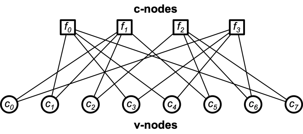
Figure 1: Tanner Graph

Figure 2: an example parity-check matrix
LDPC Decoding Algorithm
The algorithm used to decode LDPC codes was discovered independently several times and is known by different names. The most common ones are the belief propagation algorithm, the message-passing algorithm and the sum-product algorithm.
The decoding algorithms work by exchanging messages between the check and variable nodes. These messages contain a value that is proportional to the probability or the “belief” in the “correctness” of the received bit. In the first step, node c0 sends a message to f1 and f3, node c1 sends messages to f0 and f1 and so on.
In the second step, every check node fj calculates a response to every connected variable node. The response message contains the value that fj believes to be the correct one for this v-node ci assuming that the other v-nodes connected to fj are correct. In other words, if you look at the example, every c-node fj is connected to four v-nodes. So, a c-node fj looks at the message received from three v-nodes and calculates the value that the fourth v-node should have in order to fulfill the parity-check equation. At this point, if every parity-check equation is met, the algorithm terminates. Otherwise, the v-nodes receive the messages from the check nodes and use this additional information to decide if their originally received bit is OK. A simple way to do this is a majority vote.
When coming back to our example, that means that each v-node has three sources of information concerning its received bit: the original bit received and two suggestions from the check nodes. Now, the v-nodes can send another message with their updated belief for the correct value to the check nodes. This process continues until either all parity-check equations are met or we reach the maximum number of iterations that the algorithm is set to run.
The performance of the algorithm depends on various factors such as the maximum number of iterations and the numerical stability of the algorithm that arises from the multiplication of the probability (belief) values for codes with large block lengths. For this reason, logarithmic values that allow for addition instead of multiplication operations are often used. The decoding performance increases with an increasing number of iterations until it hits a point of diminishing returns.
The Need for LDPC Error Correction
Demand for ever-increasing data rates in modern communication systems continues to drive adoption of LDPC codes since they provide performance that is very close to the channel capacity for a lot of different channels and has linear-time complexity algorithms for decoding. Furthermore, they are well suited for implementation since the decoding algorithms can be heavily parallelized.
An understanding of modern forward LDPC error correction techniques is essential to the implementation of current and future communications technologies. Cardinal Peak looks forward to helping you get your bits from here to there. Learn about our signal processing expertise.