 “1-Wire to rule them all,
1-Wire to control them.
1-Wire to connect them all,
And in the circuit tie them.”
— J.R.R. Tolkien
OK, Tolkien probably didn’t write that. Nonetheless, like the One Ring of Middle Earth, 1-Wire is ancient (well, 1990s), with an interesting history and some surprisingly modern use cases. In this blog post, I’ll give you a brief technical summary of the technology, followed by a demo project on real hardware that shows how to use 1-Wire in an embedded environment. We’ll wrap up with a discussion of one very interesting and increasingly important capability: secure authentication to ensure the integrity of peripheral devices.
Contents
The 1-Wire Origin Story
![]() Dallas Semiconductor (DS) developed the basic principles of 1-Wire in the early 1990s. The communications protocol and bus timing are still sometimes referred to as the “Dallas 1-Wire Protocol.” 1-Wire parts with the “DS” prefix are still in production and date back to this early period.
Dallas Semiconductor (DS) developed the basic principles of 1-Wire in the early 1990s. The communications protocol and bus timing are still sometimes referred to as the “Dallas 1-Wire Protocol.” 1-Wire parts with the “DS” prefix are still in production and date back to this early period.
 Maxim Integrated acquired Dallas in 2001 and added about a dozen new chips to the product line over the next two decades, all with the “MAX” prefix.
![]() After acquiring Maxim in 2021, our partner Analog Devices has not yet extended the product line any further. Learn more about our solutions as an ADI design partner.
After acquiring Maxim in 2021, our partner Analog Devices has not yet extended the product line any further. Learn more about our solutions as an ADI design partner.
At this point, 98 chips are available in about two dozen different form factors. The types of 1-Wire device on the market encompass:
- Battery level gauges, protectors and monitors
- Battery ID and authentication
- Protocol converters (1-Wire to I2C, 1-Wire to UART)
- Memory (EPROM, EEPROM, ROM)
- Real-time clocks
- Secure authenticators
- Temperature/humidity sensors
A 1-Wire Bus Overview
There are many fine resources online regarding the technology’s technical specs, so I won’t delve deeply into them here. But a summary will be useful.
1-Wire is a half-duplex multidrop serial communication bus that features — you guessed it! — one wire connecting the components on the bus. Actually, that’s slightly misleading, because the components must also have a common ground connection, so “2-Wire” might be more accurate. Some types of 1-Wire devices even require a dedicated power connection separate from the data connection, so they are technically “3-Wire”. But “1-Wire” is the branding name, so we’ll stick with that.
For most devices with just a single nonground wire, 1-Wire provides both power and bidirectional communication. How is that possible? The basic idea is that the bus provides power, except during data transfer. In that case, a tiny internal capacitor in each device supplies the power. This is referred to as “parasitic power.”
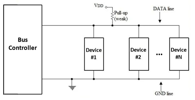
The 1-Wire bus is pulled high via a pull-up resistor, thereby providing power. Communication is done using bursts of pulses where the bus is repeatedly pulled low. The bus controller and devices have open-drain connections to the bus, meaning that they can pull the bus low (essentially shorting it to ground) but not drive it high. Pulling it high is the job of the pull-up resistor.
The bus is organized as a bus controller and some number of devices wired in parallel.
Figure 1. 1-Wire Bus Architecture
Device Internals
Diving inside a 1-Wire device, the general architecture is shown below:
Figure 2. 1-Wire Device Internals
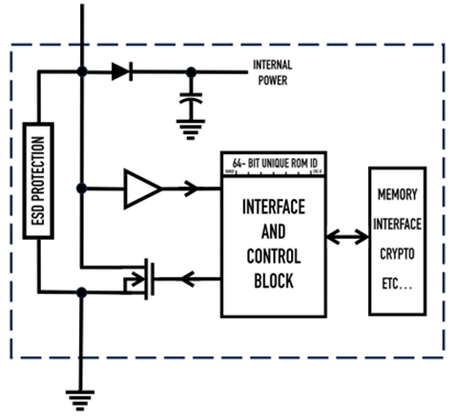
- Parasitic power is supplied via the bus, or a small internal capacitor when the bus is low.
- The buffer gate squares up the bits received from the bus.
- FET (open drain transistor) pulls the bus low to transmit a bit.
- 64-bit unique serial number, also called “Address” or “ROM ID.”
- Interface block — common to all 1-Wire devices.
- Device-specific functionality (e.g., temperature sensor), depending on the chip.
Addressing, Topology and, & Line Length
Each 1-Wire device embeds a unique 64-bit serial number consisting of an 8-bit family code, a 48-bit serial number and an 8-bit CRC. A clever device discovery mechanism enables the bus controller to gather the list of serial numbers for the devices on the bus. The mechanism uses a binary search tree and the fact that the bus is open drain. The algorithm defies a simple explanation, so check out the link above if you’re curious.
The bus accommodates relatively low speeds (15.4 kbps). A few types of 1-Wire devices additionally support an Overdrive (125 kbps) turbo mode.
Although 1-Wire networks are often quite “free form” in structure, they usually fit into a few generalized topologies.
Figure 3. 1-Wire Bus Topologies
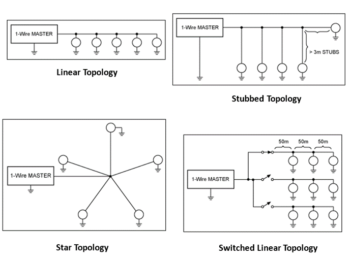
The maximum line length depends on a bunch of factors, but 200 meters is reasonable, and 500 m can be made to work with special pull-ups.
Comparing 1-Wire to SPI and I2C
SPI and I2C are the most prevalent technologies for data communication between chips. These communications protocols provide (relatively) high speed/short distance signaling between chips on the same circuit board. On the other hand, 1-Wire is slow and designed to connect an MCU to simple and potentially faraway devices. The table below has more specifics:
| Feature | 1-Wire | I2C | SPI |
|---|---|---|---|
| Number of Bus Lines (ex ground) | One | Two (SDA & SCL) | Four |
| Data Rate | ~16 Kpbs (standard) ~163 Kbps (overdrive) | 100 Kpbs to 5 Mbps | 50 Mbps |
| Pin Drive | Open Drain | Open Drain | Push Pull |
| Bus Length (w/o repeater) | >100 meters | ~1 meter | ~3m |
| ESD Protection | Built-in | No | No |
| Dedicated Clock Signal | No | Yes | Yes |
| Duplex | Half | Half | Full |
| Device Addressing | 64 Bit | 7, 8 or 9 Bit | None (use CS) |
| Multimaster | No | Yes | No |
| Power Consumption | Low | High | Medium |
| Acknowledgement Mechanism | No | Yes | No |
| Application | Brief, infrequent communications | Brief, infrequent communications | Continuous data streaming |
1-Wire Bus Controller
Three different ways to get 1-Wire functionality in an embedded project with a microcontroller (MCU) exist:
- Some MCUs have a built-in 1-Wire bus controller. In this case, bus operations are performed by reading and writing HW registers. Hardware does the difficult work of twiddling bits, so this is a very software-friendly approach.
- Our partner Analog Devices offers dedicated 1-Wire Bus Controller chips. In this case, the MCU interfaces with the bus controller over I2C. The MCU issues commands to the bus controller.
- Lastly, the protocol can be bit-banged by the MCU directly to a GPIO output pin. This method has the most software complexity and requires tight timing but is cheapest.
Our 1-Wire Sensor Demo Project: Hardware
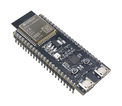
Let us now consider a real-world example. For this demo, I’ve employed an Espressif microcontroller, specifically the ESP32-S3-DevKitC-1. This small entry-level development board is equipped with an MCU with I2C and a USB interface for loading software (and other things that are not important here). Most of the I/O pins on the module are broken out to the pin headers on both sides for easy interfacing.
Figure 4. Espressif MCU DevKit (Source: Espressif)
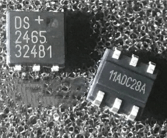
For the 1-Wire sensor interface, I used a dedicated external 1-Wire bus controller chip (DS2465) that has some cryptographic functions I didn’t use and won’t describe here.
Figure 5. DS2465 1-Wire Bus Controller (Source: AliExpress)
The interface between the Espressif MCU and the DS2465 is via an I2C bus.
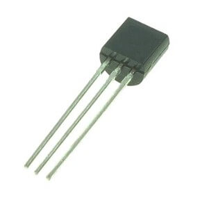
Of course, I also need a 1-Wire device on the bus. There are a lot of choices available from Analog Devices, but a few constraints helped narrow the decision. First, most 1-Wire chips are too tiny to work with by hand, so I ruled them out. Second, I didn’t want to get into exotic functionality (e.g., crypto), which is really beside this demo’s point. Third, I needed to ensure the logic level (e.g., 1.8v, 3.3v, 5v) was consistent with the DS2465 bus controller. With all this in mind, I chose a basic 3.3-volt temperature sensor (DS18S20) in a TO-92 package (i.e., “transistor package”), which has three pins (two of which are used) and is big enough to handle easily.
Figure 6. DS18S20 Temperature Sensor (Source: Mouser Electronics)
Putting the pieces together on a breadboard and adding an LED, which I’ll explain in a bit, we get:
Figure 7. 1-Wire Sensor Demo Project Breadboard
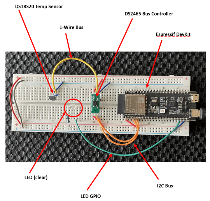
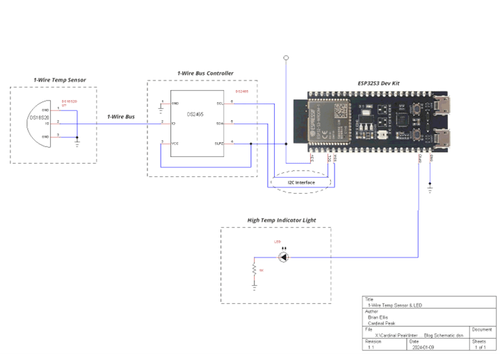
Figure 8. 1-Wire Sensor Demo Project Schematic
The 1-Wire Sensor Software Demo
Follow along with this accompanying video demonstrating the 1-Wire sensor prototype.
The software functionality is very basic:
- Init the I2C bus
- Init the 1-Wire bus controller (DS2465)
- Discover all 1-Wire devices on the bus
- Init the 1-Wire sensor for temperature (DS18S20)
- Every couple of seconds:
- Read the temperature.
- If it has changed by more than a degree or so:
- If the temp has changed, print it.
- Control the LED, as described below.
The LED functions as a high temperature indicator, and the software uses 75 degrees Fahrenheit as the high temperature. I chose 75° because making the temperature fluctuate around this number by just touching the sensor with my fingers was easy.
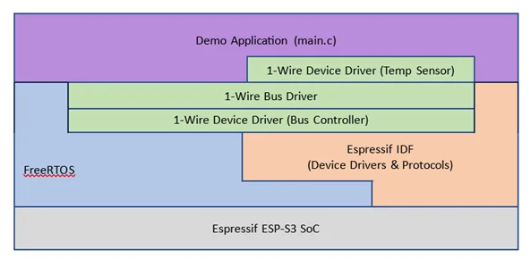
The firmware architecture is as follows:
Figure 9. 1-Wire Sensor Demo Project Software Layers
I’ve made the software available on BitBucket as open source with an MIT license. You can clone it to your local machine with git clone.
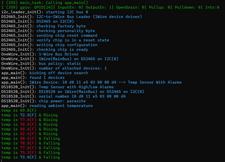
After building and flashing the code, I fired it up. The initial temperature reading was 69.8°, which is ambient for my office. I squeezed the sensor to warm it up, so you can see the successive temperate readings increase. At the point where the reading is printed in RED the LED has turned on. When the temp reached the low 80s, I let go of the sensor and allowed it to start cooling off. You can then see the successive readings drop.
Figure 10. 1-Wire Sensor Demo Project Output
At the end of the demo project, I concluded that using a 1-Wire bus in an embedded environment is not difficult (at least when using a dedicated bus controller chip), and the communications are reliable.
Harnessing the Power of a 1-Wire Sensor
Although 1-Wire technology is quite old and mature, it continues to find modern use cases, mainly in temperature sensors and so-called “authenticators.” The authenticator use case is interesting. Imagine a piece of hospital equipment with detachable accessories. The equipment vendor would like to ensure the authenticity of the accessories to prevent the use of cheap knockoffs that could jeopardize patients’ health. The 1-Wire solution to this problem? Secure authentication.
Secure authentication involves an exchange of data between the bus controller and device using a cryptographically secure protocol (public key, digital signature, Message Authentication Code (MAC), etc.) in such a way that tapping into the bus (“eavesdropping”) does not compromise the protocol. Based on data programmed into the 1-Wire device during assembly of the legitimate accessory, the device can prove that it’s genuine.
While this innovative technology enabled us to rapidly prototype a low-power temperature sensor, 1-Wire’s potential doesn’t stop there. 1-Wire can optimize and transform products across industries, from home automation to industrial sensors and beyond. If you’re ready to leverage 1-Wire to take your connected product development to the next level, our team of experts is here to help.