We recently needed a simple C++ class for linear phase FIR filtering, and I figured it might be useful to others, as well. You can download it here.
Contents
How to Use the C++ Filter Class
Here’s how to use this class:
- Specify the desired filter type (low-pass, high-pass, or band-pass) in the constructor, along with the other needed parameters: the number of taps, the transition frequencies, and the sampling frequency of the data you’ll be filtering.
- Make one call to the class’ filter function,
do_sample(), for every value in the data stream you’re filtering.do_sample()returns a filtered value each time it is called. - Use optional class helper functions as desired, for example, to load an array with the filter taps, write the taps to a file, or write the frequency response to a file.
Details on using the class are contained in the file filt.h, and the implementation is in filt.cpp. A sample program demonstrating its use on an audio file is in devel.cpp.
If all you need is code that works, you can stop here. For those who want to know how the taps are computed, keep reading. I assume that you have some exposure to digital filtering and just need a brief refresher.
Implement an FIR Filter
An FIR filter can be implemented using the following structure:
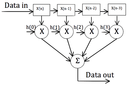
The data to be filtered is shifted into the array on the left (each box holds one data sample). Each time a new value is shifted in, the value currently stored in each position is multiplied by its corresponding tap (the “h(k)” value), and the outputs of the multipliers are summed together to yield a single data output value. The computation of each output value requires 4 multiplies and 3 adds in this four tap filter example. (The class function do_sample() performs this computation.)
The Discrete Time Fourier Transform (DTFT)
The frequency response of an N-tap FIR filter is given by the Discrete Time Fourier Transform (DTFT) of its taps. The DTFT is periodic on the interval — where corresponds to (half the sampling frequency) and is given by:
F(\omega)=\displaystyle\sum_{n=0}^{N-1}h(n)e^{-i \omega n}
The Fourier Series
The expression above for the DTFT is a weighted sum of complex sinusoids; it looks exactly like a Fourier Series.
How to Design the Taps of a Digital Filter
Therefore:
One way to design the taps of a digital filter is the following:
- Choose a desired frequency response on the interval where π corresponds to Fs / 2. Note that in the class
filt.cpp, the desired frequency response is chosen to be that of an ideal filter of the specified type. - Choose a number of taps.
- Compute the Fourier Series coefficients of the desired frequency response.
- Plot the frequency response to see how well it meets your needs (the class function
write_freqres_to_file()will output the frequency response to a file in a form suitable for plotting, for example, by using Excel).
If you are a purist, you may have noticed that the DTFT equation I gave looks like a Fourier Series but with one exception: The sign of the exponent in the complex sinusoids is negative instead of positive. But not to worry — when computing the Fourier Series coefficients, just flip the sign of the exponent in that formula too. In other words, if it is your desired frequency response, compute the taps as follows:
h(n)=\dfrac{1}{2\pi}\displaystyle\int_{-\pi}^{\pi} H(\omega)e^{i \omega n}d\omega
For the ideal frequency responses of the filters used in filt.cpp, these computations are easy. You can see the resulting formulas for the coefficients by looking at the code.
If you enjoyed this blog, subscribe to our quarterly newsletter below!